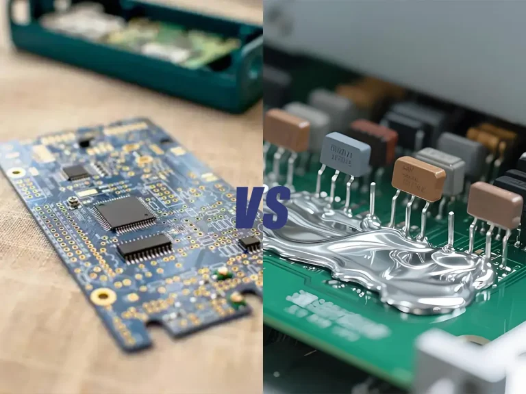
SMD components can be soldered using a temperature-controlled soldering iron, a hot air rework station, or a reflow process, depending on the package type. For most common SMD resistors, capacitors, SOICs, and small ICs, a soldering iron and flux are enough to achieve reliable solder joints.
Successful SMD soldering depends on proper heat control, component positioning, and flux usage rather than simply applying more solder or higher temperatures. This guide explains the tools, techniques, temperatures, and troubleshooting methods used for soldering surface-mount components in electronics assembly and repair.
What Are SMD Components?
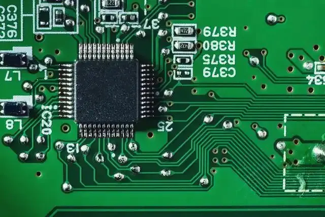
SMD (Surface Mount Device) components are electronic parts designed to be mounted directly onto the surface of a printed circuit board (PCB).
Unlike through-hole components, which require leads to pass through drilled holes, SMD components are soldered directly to copper pads on the board.
Common examples include:
- Chip resistors
- Chip capacitors
- LEDs
- Transistors
- Integrated circuits (ICs)
Because they are smaller and require less board space, SMD components are used in nearly all modern electronic products.
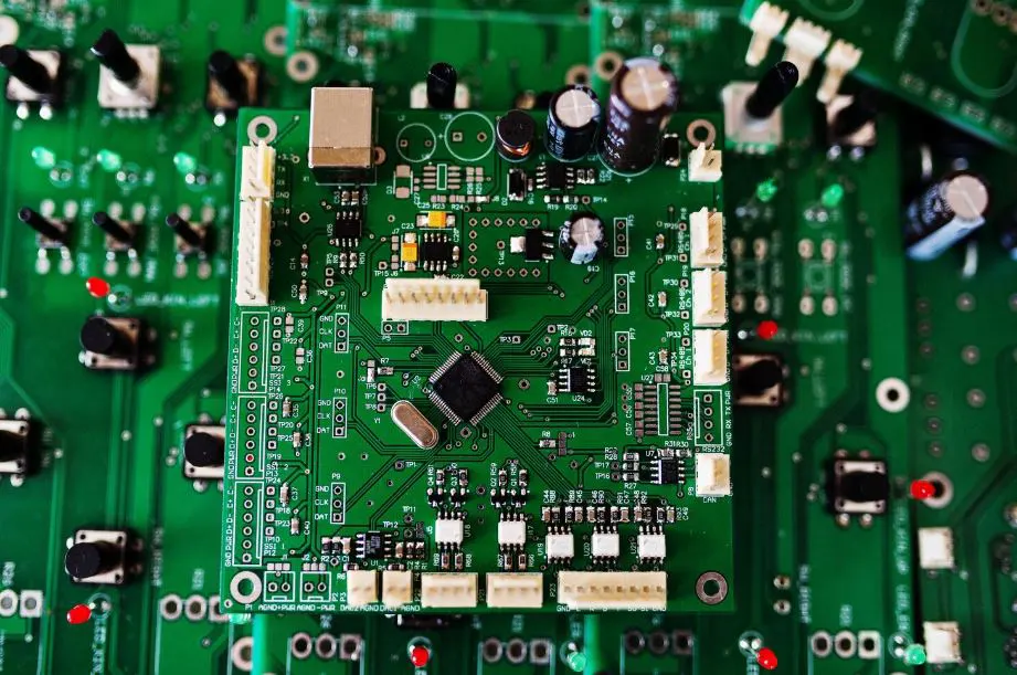
Tools Needed for SMD Soldering
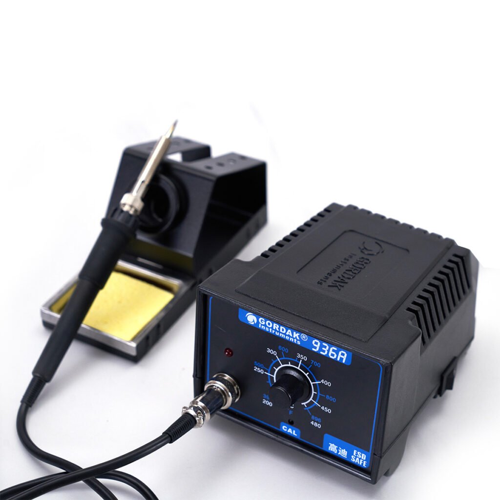
Soldering Iron
A temperature-controlled soldering station is the most important tool for manual SMD soldering.
Recommended features include:
- Stable temperature control
- Fast thermal recovery
- Replaceable soldering tips
- ESD-safe design
For most SMD work, chisel and bevel tips transfer heat more effectively than extremely fine needle tips.
Hot Air Rework Station
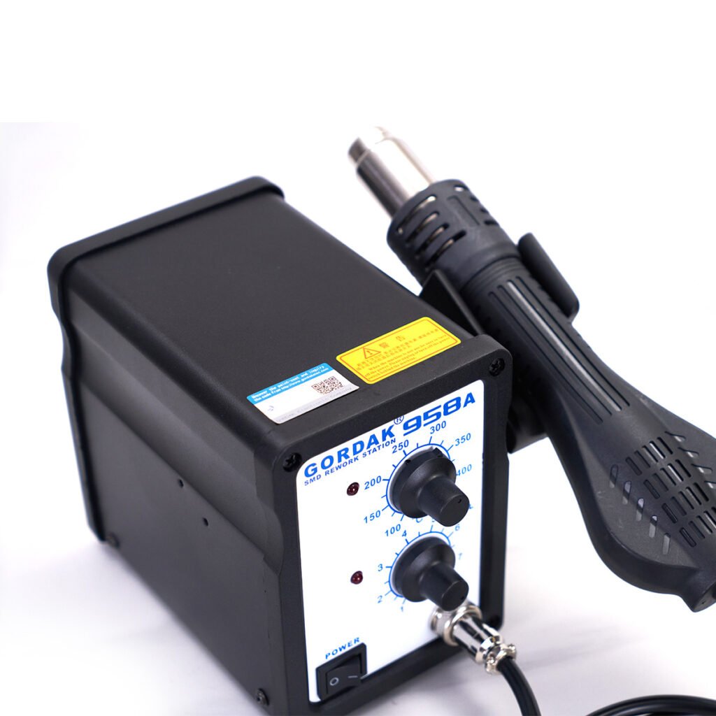
A hot air rework station heats components using controlled airflow and temperature.
It is especially useful for:
- QFN packages
- Multi-pin ICs
- Component removal
- PCB rework
Hot air allows multiple solder joints to reach reflow temperature simultaneously.
Solder Wire
Both leaded and lead-free solder can be used for SMD work.
Leaded Solder
Advantages:
- Lower melting point
- Better wetting
- Easier for beginners
Common alloy:
- Sn63/Pb37
Lead-Free Solder
Advantages:
- RoHS compliance
- Industry standard production use
Common alloys:
- SAC305
- SAC405
Lead-free solder generally requires higher working temperatures and more careful process control.
Flux
Flux is one of the most important consumables in SMD soldering.
It helps:
- Remove surface oxides
- Improve wetting
- Reduce solder bridges
- Improve heat transfer
Many soldering problems that appear to be temperature-related are actually caused by insufficient flux.
Tweezers
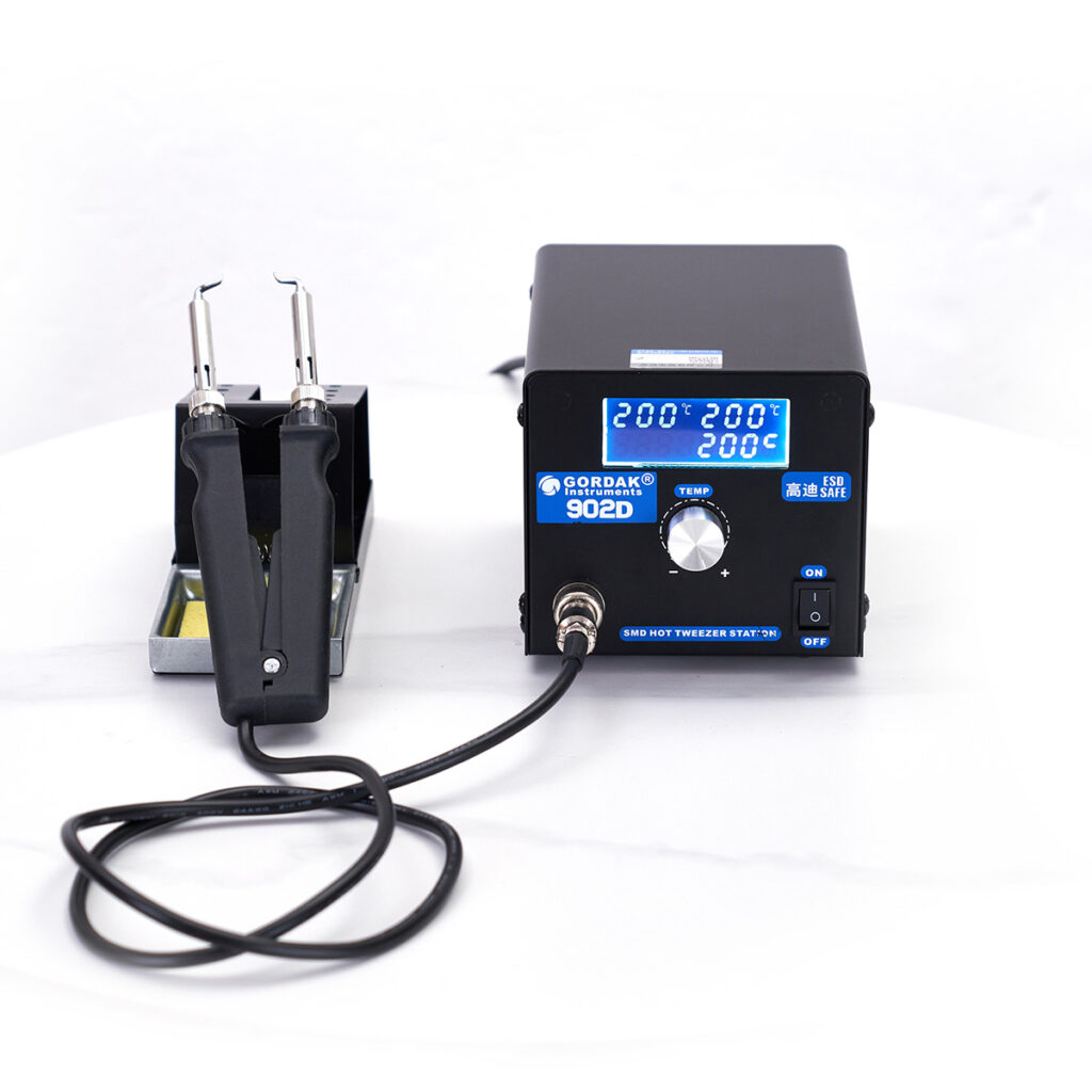
Precision tweezers are essential for positioning small components.
Fine-tip ESD-safe tweezers help:
- Align components accurately
- Hold parts during soldering
- Reduce movement during heating
Magnification and Lighting
Small solder joints are difficult to inspect with the naked eye.
Useful inspection tools include:
- Magnifying lamps
- USB microscopes
- Stereo microscopes
Good lighting improves placement accuracy and solder joint inspection.
Soldering Iron vs Hot Air Rework Station
When to Use a Soldering Iron
A soldering iron is usually the fastest and simplest option for:
- Chip resistors
- Chip capacitors
- SOIC packages
- SOT packages
- Small connectors
Most manual PCB assembly and repair work can be completed with a soldering iron and flux.
When to Use Hot Air
Hot air becomes advantageous when working with:
- QFN packages
- Bottom-pad devices
- Fine-pitch ICs
- Large multi-pin components
Because all solder joints can be heated simultaneously, alignment is often easier.
Can You Solder SMD Components Without Hot Air?
Yes.
Most SMD components can be soldered successfully using only a temperature-controlled soldering iron.
Many professional technicians routinely solder:
- 0805 resistors
- 0603 resistors
- SOIC ICs
- TSSOP ICs
without using hot air at all.
Hot air becomes more important as package complexity increases.
How to Solder SMD Components Step by Step
Step 1 – Prepare the PCB
Before soldering:
- Inspect the PCB
- Verify component orientation
- Clean dirty pads if necessary
- Apply flux to the solder pads
Flux immediately improves wetting and helps solder flow where it is needed.

Step 2 – Tin One Pad
For two-terminal components such as resistors and capacitors:
- Apply a small amount of solder to one pad.
- Avoid creating a large solder mound.
- Leave enough room for component placement.
This pre-tinned pad will be used to secure the component.
Step 3 – Position the Component
Using tweezers:
- Hold the component in position.
- Reheat the pre-tinned pad.
- Slide the component into alignment.
- Remove the soldering iron while maintaining position.
Once the solder solidifies, the component is temporarily fixed in place.
Step 4 – Solder the Remaining Connection
After the first side is secured:
- Apply flux if needed.
- Heat the opposite pad.
- Feed a small amount of solder.
- Allow solder to flow naturally around the terminal.
The finished joint should appear smooth and evenly shaped.
Step 5 – Reflow the First Side if Necessary
After completing the second side, inspect alignment.
If adjustment is needed:
- Reheat the first joint
- Reposition the component
- Allow it to cool
Proper alignment is especially important for fine-pitch packages.
Step 6 – Inspect the Solder Joint
A good solder joint typically appears:
- Smooth
- Clean
- Properly wetted
- Evenly distributed
There should be no:
- Cracks
- Voids
- Excessive solder buildup
- Bridges to neighboring pads
How to Solder Different Types of SMD Packages
Chip Resistors and Capacitors (0402, 0603, 0805, 1206)
These are usually the easiest SMD components to solder manually.
Recommended method:
- Tin one pad
- Position component
- Secure first side
- Solder second side
For beginners, 0805 and 1206 packages are significantly easier than 0402 components.
SOIC Packages
SOIC devices have visible gull-wing leads and are beginner-friendly IC packages.
Typical process:
- Align the IC
- Tack opposite corner pins
- Verify alignment
- Solder remaining pins
Flux is highly recommended.
TSSOP and TQFP Packages
These fine-pitch packages benefit from drag soldering.
The process involves:
- Applying generous flux
- Loading a small amount of solder onto the tip
- Dragging the tip across multiple pins
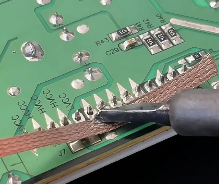
Any solder bridges can usually be removed with solder wick.
QFN Packages
QFN packages are more challenging because their leads are located underneath the device.
Common methods include:
- Hot air soldering
- Reflow soldering
- Solder paste application
Manual soldering with a standard iron is often difficult.
BGA Packages
Ball Grid Array (BGA) packages are among the most difficult SMD components to solder.
Because solder joints are hidden underneath the package, assembly typically requires:
- Solder paste
- Controlled reflow
- Specialized equipment
BGA soldering is generally not recommended for beginners.
Best Soldering Temperature for SMD Components
The ideal soldering temperature depends on the solder alloy, component size, and PCB thermal mass.
The goal is to provide enough heat for fast solder wetting without overheating the component or PCB.
Leaded Solder
For most manual SMD soldering applications:
Recommended range: 320°C–350°C
Leaded solder melts at a relatively low temperature and wets surfaces easily, making it popular for repair work and prototyping.
Benefits include:
- Faster wetting
- Lower oxidation rate
- Easier hand soldering
Lead-Free Solder
For lead-free assembly:
Recommended range: 340°C–380°C
Lead-free solder typically requires more thermal energy because of its higher melting point.
Compared with leaded solder, it:
- Flows more slowly
- Requires better temperature stability
- Produces more oxidation
Why Higher Temperature Is Not Always Better
Many beginners assume poor solder flow means the temperature should be increased.
In reality, poor results are often caused by:
- Oxidized tips
- Insufficient flux
- Incorrect tip size
- Poor heat transfer
Excessive temperature may temporarily improve solder melting but can also increase the risk of:
- Component damage
- Pad lifting
- Flux burnout
- Tip oxidation
Common SMD Soldering Problems and How to Fix Them
Even experienced technicians encounter soldering defects. Understanding the cause of each problem makes troubleshooting much easier.
Solder Bridges Between Pins
A solder bridge occurs when excess solder connects adjacent pins that should remain electrically isolated.
Common Causes
- Too much solder
- Insufficient flux
- Poor drag soldering technique
Solutions
- Apply additional flux
- Use solder wick to remove excess solder
- Reflow the pins using a clean tip
Most solder bridges can be corrected within seconds when sufficient flux is used.
Tombstoning
Tombstoning occurs when one side of a chip component lifts off the PCB during soldering.
The component stands upright, resembling a tombstone.
Common Causes
- Uneven heating
- Unequal solder volume
- Poor pad design
Solutions
- Ensure both pads heat evenly
- Use balanced solder amounts
- Reposition and reflow the component
Tombstoning is most common with smaller components such as 0402 and 0603 packages.
Cold Solder Joints
A cold solder joint forms when solder does not fully wet the pad and component lead.
Common Causes
- Low temperature
- Oxidation
- Insufficient heating time
Symptoms
- Dull appearance
- Weak mechanical connection
- Unreliable electrical performance
Solutions
- Apply fresh flux
- Reheat the joint
- Allow proper solder flow
Component Misalignment
Components may shift during soldering or reflow.
Common Causes
- Excessive hot air airflow
- Poor initial positioning
- Uneven solder surface tension
Solutions
- Reduce airflow
- Improve alignment before soldering
- Use tweezers for adjustment during reflow
Lifted PCB Pads
Lifted pads occur when the copper pad separates from the PCB surface.
Common Causes
- Excessive heat
- Excessive force
- Prolonged contact time
Prevention
- Use appropriate temperature
- Avoid prying components off the board
- Minimize heating duration
Pad damage is often much more difficult to repair than a soldering defect.
Why Flux Is Essential for SMD Soldering
Many soldering problems become significantly easier to solve when flux is used properly.
Improves Solder Wetting
Flux removes surface oxides and allows solder to flow smoothly across metal surfaces.
This creates:
- Better coverage
- Stronger joints
- Faster soldering
Reduces Oxidation
Oxides naturally form on:
- PCB pads
- Component leads
- Soldering tips
Flux helps break down these oxides during soldering.
Helps Prevent Solder Bridges
Contrary to what many beginners expect, additional flux often reduces solder bridges rather than causing them.
Proper flux allows solder to flow onto pads and leads instead of accumulating between pins.
Makes Rework Easier
Flux improves heat transfer and solder mobility during:
- Component replacement
- Bridge removal
- QFP drag soldering
- Hot air rework
For many technicians, flux is used on nearly every SMD soldering operation.
Professional Tips for Better SMD Soldering
Use Plenty of Flux
One of the biggest mistakes beginners make is trying to solder with little or no flux.
Additional flux often improves:
- Solder flow
- Joint quality
- Rework success rate
Choose the Correct Tip Size
Many people automatically select the smallest tip available.
In practice, a slightly larger tip often:
- Transfers heat more efficiently
- Speeds up soldering
- Produces better joints
The smallest tip is not always the best tip.
Keep the Tip Properly Tinned
A properly tinned tip:
- Transfers heat more efficiently
- Resists oxidation
- Improves solder wetting
Before and after soldering sessions, apply a fresh layer of solder to protect the tip surface.
Use Temperature-Controlled Equipment
Stable temperature output improves consistency.
Professional soldering stations provide:
- Faster heat recovery
- Better temperature accuracy
- Improved soldering performance
This becomes especially important when working with lead-free solder and fine-pitch components.
Practice on Larger Packages First
Beginners can build confidence by progressing from larger to smaller packages.
A practical learning path is:
- 1206 components
- 0805 components
- SOIC packages
- TSSOP packages
- TQFP packages
- QFN packages
This approach develops soldering skills gradually.
When Should You Use Hot Air Rework Instead of a Soldering Iron?
Multi-Pin ICs
Packages with many closely spaced pins are often easier to install and remove using hot air.
Examples include:
- TQFP
- QFP
- Certain QFN devices
Bottom-Pad Packages
Components containing hidden solder joints underneath the package are difficult to solder with a standard iron.
Examples include:
- QFN
- DFN
- Power management ICs
Hot air is usually the preferred solution.
Component Removal
Removing SMD components is often more difficult than installing them.
Hot air allows all solder joints to reach reflow temperature simultaneously, reducing mechanical stress on the PCB.
PCB Rework Applications
Hot air stations are commonly used for:
- IC replacement
- Connector replacement
- Repair work
- Reflow operations
For electronics repair technicians, a hot air rework station is often as important as a soldering iron.
FAQs
Yes. Packages such as 0805 resistors, capacitors, and SOIC ICs are suitable for beginners when proper tools and flux are used.
1206 and 0805 components are generally considered the easiest packages for manual soldering.
Yes. Most common SMD components can be soldered using a temperature-controlled soldering iron without hot air equipment.
Flux is strongly recommended. It improves solder wetting, reduces oxidation, and helps prevent solder bridges.
Typical ranges are:
Leaded solder: 320°C–350°C
Lead-free solder: 340°C–380°C
The exact setting depends on the application and thermal mass of the PCB.
Movement can occur because of:
Excessive airflow
Uneven heating
Surface tension effects during reflow
Proper positioning and controlled heating reduce movement.
Apply flux and use either:
Solder wick
Drag soldering techniques
A clean soldering tip
Most bridges can be removed quickly without damaging the component.
Neither tool is universally better.
A soldering iron is often faster for simple components, while hot air is preferred for complex packages, rework operations, and bottom-pad devices.
Conclusion
Soldering SMD components successfully depends on proper heat control, flux usage, and component handling rather than simply using higher temperatures or more solder. With the right tools and techniques, most common SMD packages can be soldered reliably using either a temperature-controlled soldering iron or a hot air rework station.
By understanding package-specific methods, avoiding common defects, and practicing proper soldering habits, technicians can achieve stronger solder joints, improve repair success rates, and reduce PCB damage.
Professional SMD Soldering and Rework Solutions from GORDAK
Looking for reliable equipment for PCB assembly and electronics repair? GORDAK offers professional soldering stations, hot air rework stations, and integrated rework solutions designed for precision, stability, and long-term performance.
For OEM/ODM cooperation and distributor inquiries, contact info@gordakelec.com.