Desoldering is the process of removing solder from a PCB to detach, replace, or repair electronic components. The best desoldering method depends on the component type, solder alloy, and PCB design. Common techniques include using solder wick, a desoldering pump, a hot air rework station, or a dedicated desoldering station.
When performed correctly, desoldering allows components to be removed without damaging PCB pads, traces, or surrounding parts. This guide explains the most effective desoldering methods, recommended temperatures, essential tools, and practical techniques for both through-hole and SMD components.
What Is Desoldering?
Desoldering is the reverse of soldering.
Instead of creating an electrical connection, the goal is to remove molten solder so a component can be repaired, replaced, or salvaged.
Desoldering is commonly used for:
- PCB repair
- Component replacement
- Electronics troubleshooting
- Rework operations
- Product refurbishment
- Prototyping and modifications
Successful desoldering requires controlled heat, proper tools, and patience. Excessive force often causes more damage than the solder itself.
Tools Used for Desoldering
Different tools are designed for different desoldering tasks.
Solder Wick (Desoldering Braid)
Solder wick is a braided copper ribbon that absorbs molten solder through capillary action.
Best for:
- Removing excess solder
- Cleaning solder bridges
- Clearing PCB pads
- Fine-pitch IC cleanup
Advantages:
- Inexpensive
- Easy to use
- Precise solder removal
Limitations:
- Less effective on large solder joints
- Requires good heat transfer
Desoldering Pump
A desoldering pump uses vacuum suction to remove molten solder.
Best for:
- Through-hole components
- Connectors
- Large solder joints
Advantages:
- Fast solder removal
- Affordable
- Effective for through-hole work
Limitations:
- Less effective on fine-pitch SMD components
- Requires proper timing
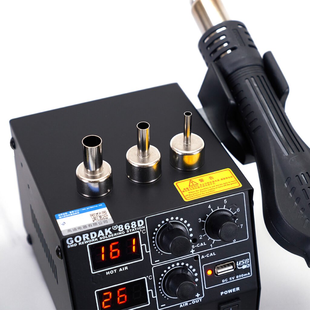
Hot Air Rework Station
A hot air station removes components by heating multiple solder joints simultaneously.
Best for:
- SMD components
- IC packages
- QFP devices
- QFN devices
- Connectors
Advantages:
- Even heating
- Reduced mechanical stress
- Ideal for modern electronics
Limitations:
- Requires temperature and airflow control
- Can affect nearby components if used improperly
Desoldering Station
A desoldering station combines heating and vacuum extraction in a single tool.
Best for:
- High-volume repair work
- Through-hole PCB assembly
- Production environments
Advantages:
- Fast operation
- Efficient solder removal
- Consistent results
Limitations:
- Higher cost
Best Desoldering Temperatures
Temperature selection depends on the solder alloy and application.
Leaded Solder
Typical soldering station settings:
320°C–350°C
Leaded solder generally melts more easily and requires less thermal energy.
Lead-Free Solder
Typical soldering station settings:
350°C–380°C
Lead-free solder has a higher melting point and often requires additional flux for efficient removal.
Hot Air Rework Temperatures
Typical starting ranges:
Leaded Components
280°C–320°C
Lead-Free Components
320°C–380°C
Actual settings vary based on:
- PCB thickness
- Component size
- Nozzle size
- Airflow settings
Higher temperatures are not always better. Controlled heating is usually safer and more effective.
How to Desolder Through-Hole Components
Through-hole components can be challenging because solder fills the plated hole and surrounds the component lead.
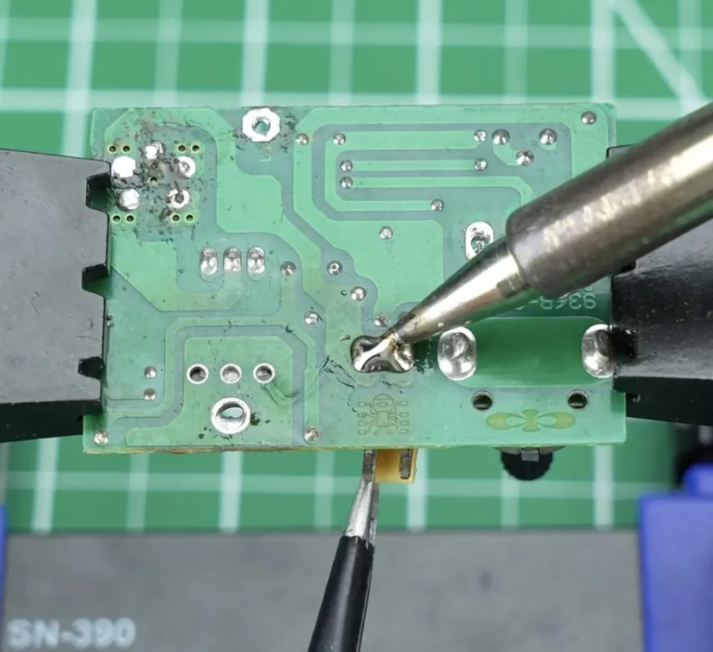
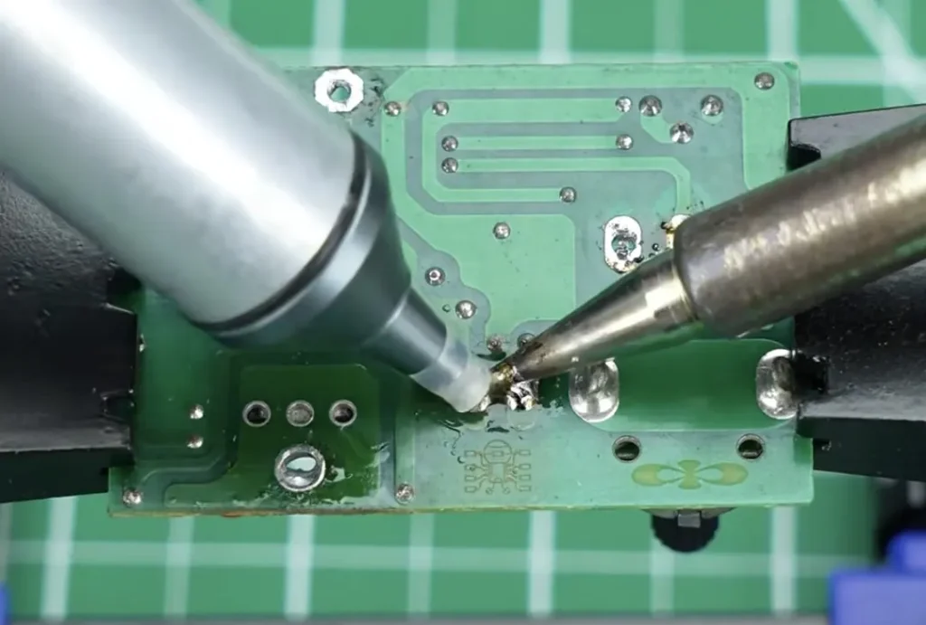
Method 1: Using a Desoldering Pump
This is one of the most common techniques.
Step 1
Heat the solder joint until the solder fully melts.
Step 2
Position the pump nozzle close to the molten solder.
Step 3
Trigger the pump to remove the solder.
Step 4
Repeat if necessary until the hole is clear.
This method works well for:
- Resistors
- Capacitors
- Connectors
- Switches
Method 2: Using Solder Wick
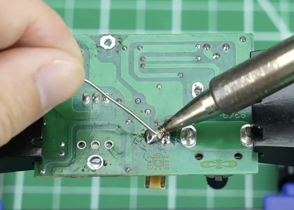
Solder wick is useful when small amounts of solder remain after using a pump.
Step 1
Apply flux to the joint.
Step 2
Place the braid over the solder.
Step 3
Press the soldering iron tip onto the braid.
Step 4
Allow the solder to flow into the wick.
Step 5
Remove the braid and inspect the hole.
This method provides cleaner results but may require more time.
Method 3: Adding Fresh Solder First
Many technicians add fresh solder before attempting removal.
Fresh solder:
- Improves heat transfer
- Re-activates flux
- Helps old solder melt more evenly
This technique is especially useful when working with aged or oxidized solder joints.
How to Desolder SMD Components
SMD components require different techniques because their solder joints are located on the PCB surface.
Removing SMD Resistors and Capacitors
Small passive components are often the easiest to remove.
Method
- Apply flux.
- Heat both sides of the component.
- Lift the component gently with tweezers.
- Clean the pads afterward.
For larger components, hot air may be more effective.
Removing SOIC and TSSOP ICs
Integrated circuits with exposed pins can often be removed using either a soldering iron or hot air station.
Using Hot Air
- Apply flux.
- Heat the component evenly.
- Wait for solder reflow.
- Lift the IC carefully with tweezers.
Avoid pulling before the solder has fully melted.
Removing QFP Components
Fine-pitch QFP packages are typically removed using hot air.
Even heating is important because all pins must reach reflow temperature simultaneously.
Excessive force can easily lift PCB pads.
Removing QFN Components
QFN packages often contain hidden solder joints underneath the device.
Because the solder cannot be accessed directly with a soldering iron, hot air is usually required.
The PCB should be heated evenly until the component can be lifted without resistance.
How to Remove IC Chips Safely
Removing ICs requires more care than removing simple resistors or capacitors. Integrated circuits often have many solder joints, making uneven heating a common cause of PCB damage.
Apply Flux Before Heating
Flux improves heat transfer and helps solder reach a uniform molten state.
Benefits include:
- Faster solder melting
- Reduced oxidation
- Lower risk of pad damage
- Easier component removal
For most IC removal jobs, flux should be applied before any heat is introduced.
Heat the Entire Package Evenly
One of the biggest mistakes is focusing heat on only one side of the IC.
Uneven heating can cause:
- Bent leads
- Lifted pads
- Damaged traces
When using hot air, move the nozzle in small circular motions to distribute heat evenly across the package.
Never Force a Component Off the PCB
If an IC does not lift easily, the solder has not fully reflowed.
Forcing removal can cause:
- Lifted pads
- Broken traces
- PCB delamination
A properly heated component should lift with almost no resistance.
Clean Remaining Solder
After removing the component:
- Apply fresh flux.
- Use solder wick to remove remaining solder.
- Inspect the pads carefully.
- Prepare the PCB for replacement or repair.
Clean pads make the next soldering operation significantly easier.
How to Avoid PCB Damage During Desoldering
Most PCB damage occurs because of excessive heat or excessive force rather than the desoldering process itself.
Avoid Excessive Temperature
Higher temperatures do not always produce better results.
Excessive heat may cause:
- Pad lifting
- Burned solder mask
- Delamination
- Component damage
Use only enough heat to achieve efficient solder melting.
Minimize Heating Time
Heat exposure should be controlled.
Instead of holding the iron on a joint for an extended period:
- Improve heat transfer
- Use appropriate tip sizes
- Apply flux
Efficient heat transfer is safer than prolonged heating.
Support the PCB Properly
Large or flexible boards should be supported during repair.
Unsupported boards may flex during component removal, increasing stress on pads and traces.
Use the Correct Tool for the Job
Trying to remove a QFN package with only a soldering iron often creates unnecessary risk.
Similarly, using hot air for a simple through-hole resistor may be inefficient.
Selecting the proper desoldering method improves both speed and safety.
Common Desoldering Problems and Solutions
Even experienced technicians occasionally encounter difficulties.
Understanding the root cause helps avoid frustration and PCB damage.
Solder Won’t Melt
Possible Causes
- Temperature too low
- Lead-free solder
- Large copper planes
- Poor heat transfer
- Oxidized soldering tip
Solutions
- Increase temperature slightly
- Use a larger tip
- Apply fresh flux
- Add a small amount of fresh solder
Fresh solder often improves heat transfer and helps stubborn joints melt more easily.
Component Won’t Come Off
Possible Causes
- Hidden solder joints
- Incomplete reflow
- Insufficient heating
Solutions
- Continue heating evenly
- Add flux
- Inspect for remaining solder connections
Never pull on a component that still feels attached.
PCB Pad Starts Lifting
Possible Causes
- Excessive force
- Excessive heat
- Prolonged contact time
Solutions
- Stop immediately
- Allow the area to cool
- Reassess the removal method
Once a pad lifts, repair becomes significantly more difficult.
Nearby Components Move During Hot Air Rework
Possible Causes
- Airflow too high
- Excessive heating time
Solutions
- Reduce airflow
- Use a smaller nozzle
- Shield nearby components when necessary
Proper airflow control is just as important as temperature control.
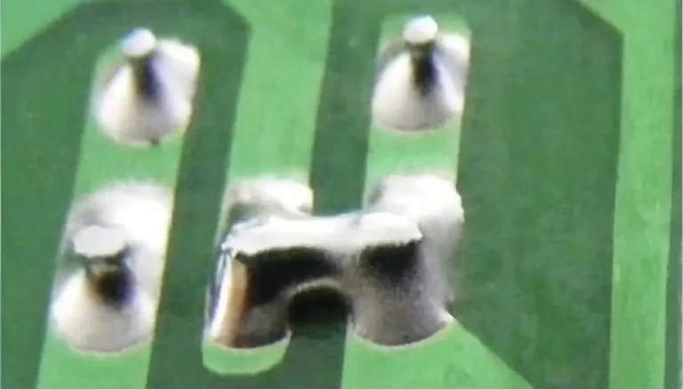
Why Does Solder Get Stuck in Through-Holes?
This is one of the most common desoldering challenges.
Even after removing most of the solder, some remains trapped inside the plated through-hole.
Cause 1: Barrel Adhesion
Molten solder wets the copper barrel inside the hole.
As it cools, some solder remains attached to the plating.
Cause 2: Insufficient Vacuum
A desoldering pump may remove only part of the molten solder.
Small amounts can remain trapped inside the hole.
Cause 3: Multilayer PCBs
Multilayer boards often contain internal copper planes that absorb heat rapidly.
This makes solder removal more difficult.
Solutions
- Add fresh solder first
- Apply additional flux
- Reheat thoroughly
- Use solder wick after vacuum extraction
Sometimes multiple cycles are required to completely clear a plated hole.
Hot Air vs Solder Wick vs Desoldering Pump
Each method serves a different purpose.
Solder Wick
Best for:
- Cleaning pads
- Removing solder bridges
- Fine-pitch IC work
Advantages:
- Precise
- Low cost
- Excellent cleanup tool
Desoldering Pump
Best for:
- Through-hole components
- Large solder joints
Advantages:
- Fast solder removal
- Easy to use
- Affordable
Hot Air Rework Station
Best for:
- SMD components
- IC removal
- Connectors
- Modern PCB repair
Advantages:
- Simultaneous heating
- Reduced mechanical stress
- Effective for complex packages
Many professional repair technicians use all three tools because each has situations where it performs best.
Professional Desoldering Tips
Add Fresh Solder Before Removal
This may seem counterintuitive, but fresh solder improves heat transfer and often makes removal easier.
Use Plenty of Flux
Flux is one of the most effective desoldering aids available.
It improves:
- Wetting
- Heat transfer
- Solder flow
Keep Tips Clean and Tinned
A properly maintained tip transfers heat more efficiently and reduces desoldering time.
Use the Largest Practical Tip
Larger tips generally transfer heat more effectively than extremely small tips.
Improved heat transfer often allows lower temperature settings.
Practice Heat Control
Professional technicians focus on controlled heating rather than maximum temperature.
Good heat management:
- Protects PCB pads
- Reduces oxidation
- Improves repair success rates
FAQs
For through-hole components, a desoldering pump is often the easiest solution. For SMD components, a hot air rework station is usually the most effective method.
Yes. Solder wick, hot air, and specialized low-melting-point alloys can all be used successfully.
Fresh solder improves heat transfer and helps old solder melt more uniformly. This often makes solder removal significantly easier.
For many SMD components, yes. Hot air can heat multiple joints simultaneously, making removal easier and reducing mechanical stress.
Solder often remains attached to the plated barrel of a through-hole. Additional flux, fresh solder, and repeated extraction may be necessary.
Yes. Improper technique may cause: Lifted pads, Broken traces, Burned solder mask, Delamination.
Controlled heating and patience are essential.
Conclusion
Desoldering is an essential skill for electronics repair, PCB rework, and component replacement. Whether working with through-hole parts, SMD components, or complex IC packages, selecting the right tools and techniques greatly improves success rates.
Solder wick, desoldering pumps, and hot air rework stations each have specific strengths. Understanding when to use each method helps reduce PCB damage, speed up repairs, and produce cleaner results.
By focusing on proper heat control, adequate flux usage, and careful component handling, technicians can remove components efficiently while protecting the integrity of the PCB.
Professional Soldering and Rework Solutions from GORDAK
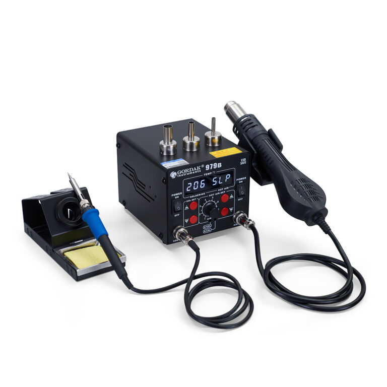
Need reliable equipment for PCB repair, rework, and electronics assembly? GORDAK offers professional soldering stations, hot air rework stations, and integrated rework solutions designed for precise temperature control and dependable performance.
For OEM/ODM cooperation and distributor inquiries, contact info@gordakelec.com.