Have you ever heard about micro soldering? Micro soldering is a relatively complex process, but this shouldn’t have to prevent you from finding the optimal soldering process for your needs. In line with this thought, today, we’re looking at some of the key things you need to know about micro soldering, including what it is, how it works, and why it might be a good option for your needs.
What is Micro Soldering?
First of all, we need to define what micro soldering actually is. Simply put, micro soldering is a when ultra-fine wires are joined through the application of heat, fusing the two wires together. This is largely similar to regular soldering processes.
Compared to regular soldering, micro soldering works with far smaller equipment, making it often trickier than regular soldering with much more room for human error. Hence, micro soldering often requires a microscope to accurately solder parts together.

How Does Micro Soldering Differ From Regular Soldering?
As we’ve briefly mentioned already, micro soldering differs from regular soldering in that it works with very small and delicate parts – and this accordingly presents a range of unique complications and challenges.
Of course, as modern technology advances, the prevalence of micro components is becoming greater and greater, increasing the demand for micro soldering skills. As such, it’s safe to say that micro soldering has become an increasingly reliable and popular option as a result.
What Tools Do You Need for Micro Soldering?
Micro soldering requires more than a standard soldering iron. Because the components and solder joints are extremely small, the right combination of tools can make the work significantly easier and more precise.
The basic micro soldering setup typically includes:
- Microscope or magnification system – Provides a clear view of small pads, leads, and components.
- Temperature-controlled soldering station – Allows precise control of the soldering iron temperature.
- Fine soldering tips – Small tips provide better access to fine-pitch components and narrow solder joints.
- Fine solder wire and flux – Flux improves solder flow and helps remove oxidation from the working area.
- Precision tweezers – Used to position and hold small components during soldering.
- Hot air rework station – Useful for removing and reworking SMD components with multiple solder joints.
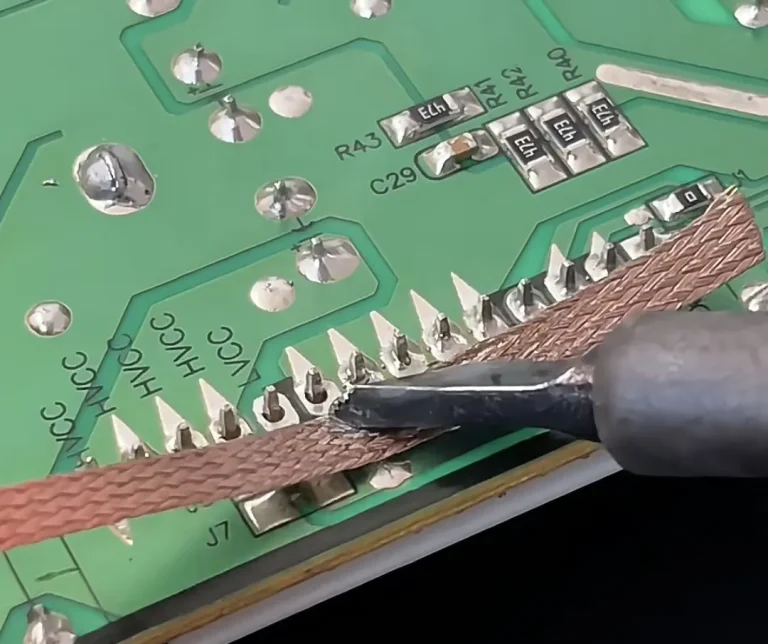
- Desoldering wick – Helps remove excess solder from pads after component removal.
- ESD protection – An anti-static mat and wrist strap help reduce the risk of electrostatic discharge when working with sensitive electronics.
For beginners, a temperature-controlled soldering station, microscope, fine-tip tweezers, flux, and suitable solder should form the core of the workstation. A hot air rework station becomes particularly useful when working with multi-pin SMD components or components that are difficult to remove with an iron alone.
How to Micro Solder: Step-by-Step
Micro soldering requires controlled movements, accurate positioning, and careful heat management. The following workflow can help beginners build a more reliable micro soldering process.
Step 1: Secure and Inspect the PCB
Place the PCB securely on an ESD-safe work surface and inspect the target area under a microscope.
Make sure you can clearly identify:
- The component to be soldered
- The surrounding pads
- Nearby components
- Any damaged or contaminated areas
A stable PCB is important because even small movements become significant when working with microscopic solder joints.
Step 2: Clean the Soldering Area
Clean the target area with an appropriate electronics-grade cleaning solution, such as isopropyl alcohol, and allow the board to dry completely.
Removing dirt, oxidation, and flux residue helps improve solder flow and makes the solder joint easier to inspect.
Step 3: Apply a Small Amount of Flux
Apply a controlled amount of flux to the soldering area.
Flux helps solder flow across the pad and component lead while reducing oxidation during heating. Avoid applying excessive flux, especially around densely populated areas.
Step 4: Tin the Tip and Prepare the Solder
Select a fine soldering tip that provides enough access to the target joint without unnecessarily contacting nearby components.
Lightly tin the tip before soldering. This improves heat transfer between the tip and the soldering area.
Use a small-diameter solder wire when working with very small components so that you can control the amount of solder more accurately.
Step 5: Position the Component
Use precision tweezers to position the component accurately on the PCB.
For small components, alignment is critical. Check the orientation and make sure the component is sitting correctly on the intended pads before applying solder.
Step 6: Solder the Component
Bring the soldering tip to the joint and apply a small amount of solder.
Avoid holding the tip on the pad for longer than necessary. The objective is to transfer enough heat to form a reliable joint without unnecessarily heating the PCB or surrounding components.
For fine-pitch components, work carefully from one joint or lead to the next while monitoring the solder flow under magnification.
Step 7: Inspect the Solder Joint
After soldering, inspect the joint under the microscope.
Look for:
- Insufficient solder
- Excessive solder
- Solder bridges
- Poor alignment
- Incomplete wetting
- Damaged pads or component leads
If necessary, use flux and desoldering wick to correct excess solder.
Step 8: Clean and Test the Board
After completing the soldering work, remove remaining flux residue using an appropriate cleaning method.
Then inspect the repaired area again and, where appropriate, use a multimeter or other suitable test equipment to verify electrical continuity before returning the board to service.
Micro Soldering Temperature and Tip Selection
Temperature and soldering tip selection can have a major impact on micro soldering results. Because micro components and PCB pads are sensitive to excessive heat, the goal is to use enough heat to form the solder joint without unnecessarily heating the surrounding area.
Choose the Temperature Based on the Solder
The correct temperature depends on the solder alloy, component, PCB design, and soldering technique.
As a starting point:
| Solder Type | Typical Starting Range |
|---|---|
| Leaded solder | 300–350°C |
| Lead-free solder | 330–380°C |
These values are starting points rather than universal settings. Always consider the component manufacturer’s thermal limits and adjust the temperature based on the actual soldering response.
Choose the Right Tip
A fine tip is useful when working with small pads and fine-pitch components, but the smallest possible tip is not always the best choice.
Choose a tip that:
- Provides sufficient access to the joint
- Transfers heat efficiently
- Does not interfere with adjacent components
- Allows controlled solder application
For very small components, a fine conical or small chisel tip may provide better control depending on the application.
When Should You Use Hot Air for Micro Soldering?
A soldering iron is often the primary tool for micro soldering, but a hot air rework station can be useful when working with components that have multiple solder joints.
Use a soldering iron when:
- Soldering individual pads or leads
- Repairing fine wires
- Performing jumper wire repairs
- Making precise corrections to individual solder joints
Use a hot air rework station when:
- Removing multi-pin SMD components
- Reworking small IC packages
- Reflowing multiple solder joints simultaneously
- Removing components without applying mechanical force to individual leads
For more complex repairs, technicians may use both tools. Hot air can be used to remove or reposition an SMD component, while a fine-tip soldering iron can then be used for detailed soldering and correction work.
The key is not to replace one tool with the other, but to use each tool where it provides the best control.
Common Micro Soldering Mistakes to Avoid
Micro soldering leaves very little room for error. Common mistakes can damage pads, components, or the PCB.
Using Too Much Solder
Excess solder can create bridges between closely spaced pads. Apply only enough solder to form a reliable joint.
Using Excessive Heat
High temperature does not necessarily make micro soldering faster. Excessive heat can damage components, lift PCB pads, or affect nearby components.
Applying Too Much Flux
Flux helps improve solder flow, but excessive amounts can make the working area difficult to control and clean.
Choosing the Wrong Soldering Tip
A tip that is too large may contact nearby components, while a tip that is too small may transfer heat inefficiently.
Skipping Microscope Inspection
A solder joint may look acceptable to the naked eye but still contain a bridge, insufficient solder, or poor alignment. Always inspect fine solder joints under suitable magnification.
Moving the Component Before the Solder Solidifies
Component movement during cooling can create unreliable or uneven solder joints. Allow the solder to solidify before making final adjustments.
FAQs
Micro soldering is a precision soldering technique used to work with very small electronic components, fine pads, wires, and connections that require magnification and controlled soldering equipment.
Start with a temperature-controlled soldering station, fine soldering tip, suitable solder and flux, precision tweezers, and a microscope or other suitable magnification system. Practice on scrap PCBs before working on valuable electronics.
For very small components and fine-pitch connections, a microscope or suitable magnification system can make positioning, soldering, and inspection significantly easier.
There is no single temperature that works for every micro soldering application. The appropriate setting depends on the solder alloy, PCB, component, and technique. Start conservatively and adjust the temperature based on solder flow and the manufacturer’s thermal specifications.
Yes. A hot air rework station can be useful for removing and reworking small SMD components, especially components with multiple solder joints. A soldering iron remains useful for precise individual joints and fine corrections.
Micro soldering involves much smaller components, pads, wires, and solder joints. It generally requires greater visual magnification, finer tools, and more precise heat and solder control than conventional soldering.
Final Thoughts
If you have been looking for the right type of soldering method for your needs, it may be worth considering micro soldering to see how this could work for you. Of course, it’s worth noting here that micro soldering requires a very steady hand and caution due to the intricate nature of the work. Nonetheless, it can be an incredibly useful tool in many cases, especially for people who need a reliable way of securing wires and the like for micro components.
As such, starting with the highest quality soldering equipment is integral to ensure you’re getting the most from your micro soldering efforts. Fortunately, this is where our teams can help; so if you need any further support with your own soldering efforts, contact us today at info@gordakelec.com!