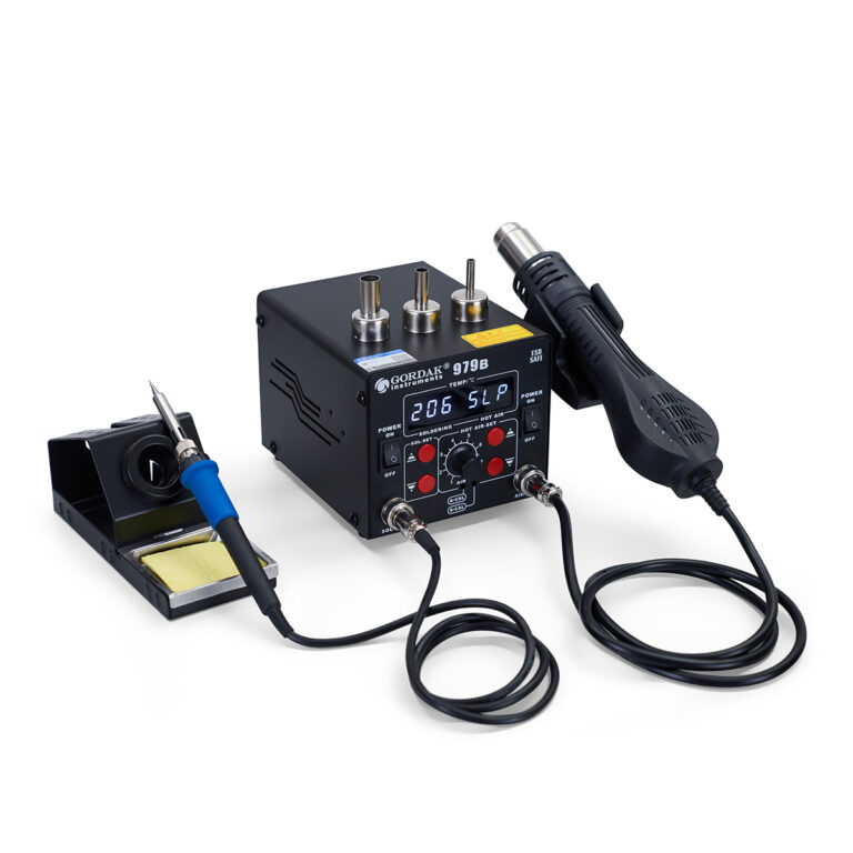
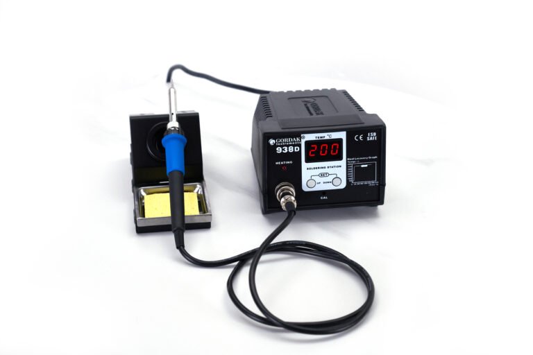
A solder bridge is an unintended connection of solder between two conductors that should remain electrically isolated. Solder bridges commonly occur between adjacent PCB pads, IC pins, or component leads and can cause short circuits, malfunctioning circuits, or complete device failure.
Most solder bridges are caused by excessive solder, insufficient flux, improper soldering technique, incorrect temperature control, or poor PCB design. Fortunately, they are usually easy to identify, remove, and prevent with proper soldering practices.
This guide explains what solder bridges are, why they happen, how to repair them, and how to avoid them during PCB assembly and repair.
What Is a Solder Bridge?
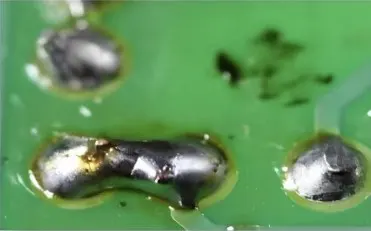
A solder bridge occurs when molten solder creates an unintended electrical connection between two adjacent conductive points.
Common locations include:
- Fine-pitch IC pins
- SMD component pads
- Through-hole component leads
- Connector terminals
Because solder is electrically conductive, even a small bridge can create a short circuit that prevents a PCB from functioning properly.
In severe cases, solder bridges may result in:
- Device startup failures
- Signal interference
- Excessive current draw
- Component damage
- Complete circuit failure
Some solder bridges are visible to the naked eye, while others may require magnification to detect.
Why Do Solder Bridges Happen?
Understanding the cause is the first step toward preventing future defects.
Excessive Solder Application
The most common cause of solder bridges is simply applying more solder than necessary.
When excess solder is introduced into a joint, molten solder may flow across neighboring pads or pins and solidify as a bridge.
This is particularly common when soldering:
- QFP packages
- TQFP packages
- Fine-pitch connectors
- Small SMD components
More solder does not create a stronger joint. In most cases, only a small amount of solder is required.
Insufficient Flux
Many beginners blame solder bridges on excess solder alone, but insufficient flux is often the real problem.
Flux improves:
- Wetting
- Surface tension control
- Solder flow
Without enough flux, solder tends to cling randomly between pins instead of flowing neatly onto pads and leads.
This is why professional technicians often apply additional flux when removing solder bridges.
Incorrect Soldering Technique
Poor technique can easily create bridging.
Common examples include:
- Feeding solder directly between pins
- Holding the solder wire on the joint too long
- Applying heat unevenly
- Dragging solder across pins without flux
Even experienced technicians can create bridges when working on fine-pitch packages without proper technique.
Oxidized Soldering Tips
An oxidized tip transfers heat inefficiently.
Poor heat transfer often causes:
- Uneven solder flow
- Excess solder buildup
- Difficulty controlling molten solder
If solder does not wet the tip properly, bridging becomes more likely.
Improper Temperature Settings
Both low and excessively high temperatures can contribute to bridging.
Low temperatures may cause:
- Slow wetting
- Excess solder accumulation
High temperatures may cause:
- Flux burnout
- Poor solder control
- Increased oxidation
Stable temperature control is generally more important than simply increasing temperature.
PCB Design and Manufacturing Issues
Not all solder bridges are caused by the technician.
Some may result from:
- Insufficient pad spacing
- Poor stencil design
- Excess solder paste deposition
- Improper reflow profiles
These issues are more common in production environments than in manual repair work.
Types of Solder Bridges
Different soldering processes produce different types of bridges.
Understanding the differences helps identify the underlying cause.
SMD Solder Bridges
These are the most common bridges encountered during electronics assembly and repair.
Typical locations include:
- IC pins
- SMD resistors
- Capacitors
- Fine-pitch packages
Because modern electronics use increasingly smaller components, SMD bridging is a frequent challenge.
Through-Hole Solder Bridges
Through-hole bridges occur when solder connects adjacent component leads on the underside of a PCB.
Common causes include:
- Excess solder
- Closely spaced pins
- Poor soldering angle
Although generally easier to repair than SMD bridges, they can still cause significant electrical problems.
Fine-Pitch IC Bridges
Fine-pitch packages such as:
- TQFP
- QFP
- TSSOP
have very small lead spacing.
Even a tiny excess of solder may create bridges between adjacent pins.
These packages often require:
- Flux-assisted drag soldering
- Solder wick cleanup
- Careful inspection
Wave Soldering Bridges
Wave solder bridges typically occur during automated through-hole assembly.
Contributing factors may include:
- Conveyor angle
- Solder wave characteristics
- Flux quantity
- Lead spacing
Unlike hand soldering bridges, these defects are usually process-related rather than operator-related.
How to Identify a Solder Bridge
Not every soldering defect is obvious.
Careful inspection is important before powering a PCB.
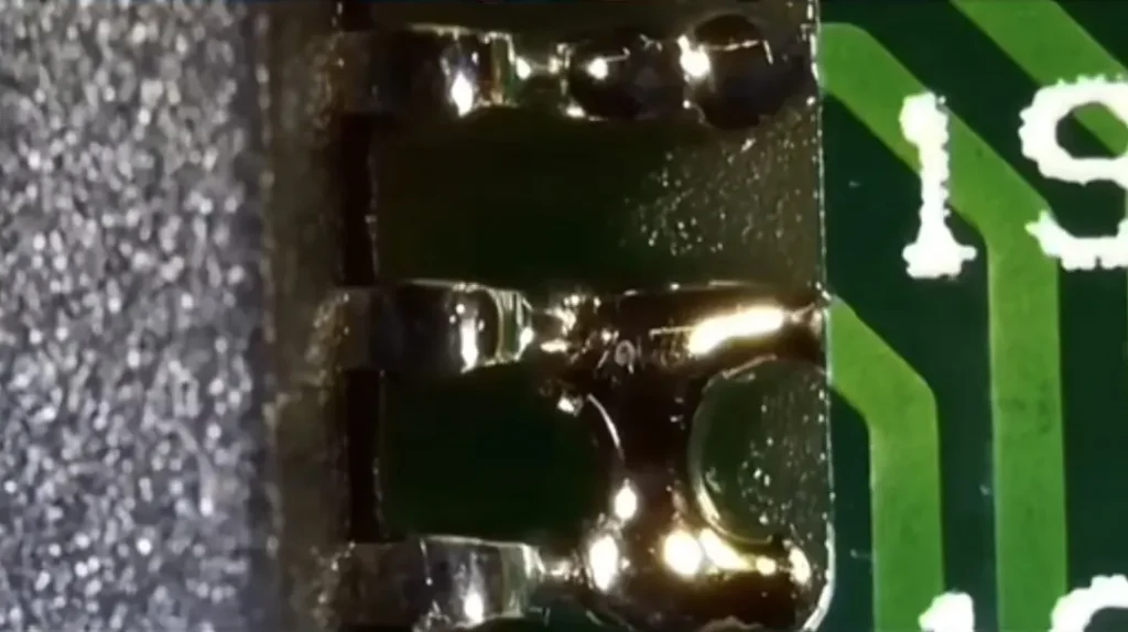
Visual Inspection
The first step is simply looking closely at the solder joints.
Signs include:
- Visible solder connections between pins
- Uneven solder accumulation
- Excessive solder fillets
A magnifier or microscope significantly improves detection accuracy.
Electrical Testing
A multimeter can help confirm suspected bridges.
Continuity testing is especially useful when:
- Pins are closely spaced
- The bridge is difficult to see
- The PCB fails unexpectedly
Testing before power-up can prevent further damage.
Functional Symptoms
Sometimes the first indication of a solder bridge is abnormal circuit behavior.
Common symptoms include:
- PCB not powering on
- Unexpected resets
- Communication failures
- Excessive current consumption
- Overheating components
Whenever these symptoms appear after soldering, inspect for bridges immediately.
How to Remove a Solder Bridge
The best repair method depends on the component type, pin spacing, and amount of excess solder. In most cases, solder bridges can be removed without damaging the PCB if proper tools and techniques are used.
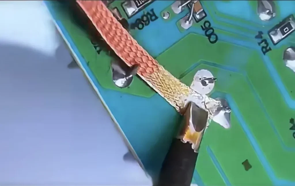
Method 1: Use Solder Wick
Solder wick (desoldering braid) is one of the most effective ways to remove excess solder from bridged pins.
Steps
- Apply flux to the bridged area.
- Place the solder wick directly over the bridge.
- Position the soldering iron tip on top of the wick.
- Allow the solder to flow into the braid.
- Remove the wick and inspect the joint.
The copper braid absorbs molten solder through capillary action, leaving behind cleaner joints.
Common Mistakes
Avoid:
- Pressing too hard
- Holding heat too long
- Reusing saturated braid
Excessive heat or pressure can lift PCB pads and damage fine-pitch components.
Method 2: Add Flux and Reflow the Joint
Many small solder bridges can be removed without solder wick.
Steps
- Apply a generous amount of flux.
- Clean the soldering tip.
- Reheat the bridged pins.
- Allow surface tension to pull solder back onto individual leads.
This method often works surprisingly well on fine-pitch ICs.
The reason is simple: properly activated flux helps solder flow where it belongs instead of remaining trapped between pins.
Method 3: Drag Soldering Repair
Drag soldering is commonly used for repairing bridges on QFP, TQFP, and TSSOP packages.
Steps
- Apply flux across the entire row of pins.
- Use a clean chisel or bevel tip.
- Lightly drag the tip along the leads.
- Allow excess solder to collect on the tip.
When performed correctly, surface tension naturally pulls solder onto the pins while reducing bridging.
This technique is widely used by professional technicians working with fine-pitch ICs.
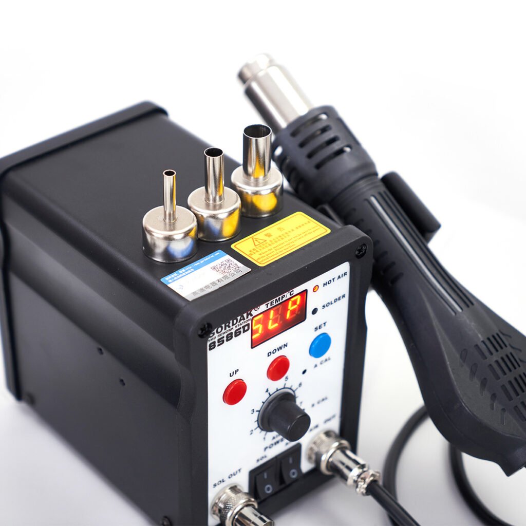
Method 4: Use Hot Air Rework
For severe bridging or difficult packages, a hot air rework station may provide better results.
Suitable Applications
- QFN packages
- Fine-pitch ICs
- Multi-pin devices
- Dense PCB assemblies
General Process
- Apply flux.
- Heat the area evenly with controlled airflow.
- Allow solder to reflow.
- Let surface tension redistribute the solder.
Hot air is particularly useful when multiple bridged pins are involved.
However, airflow and temperature must be controlled carefully to avoid moving nearby components.
Why Flux Is So Important When Removing Solder Bridges
Many people assume solder bridges are caused only by too much solder.
In reality, insufficient flux is often a major contributing factor.
Flux helps by:
- Reducing surface oxidation
- Improving wetting
- Controlling solder flow
- Enhancing heat transfer
When technicians encounter stubborn bridges, the first solution is often not more heat—it is more flux.
This is especially true when working with:
- Lead-free solder
- Fine-pitch ICs
- Oxidized solder joints
How to Prevent Solder Bridges
Preventing bridges is far easier than repairing them.
Good soldering habits significantly reduce the likelihood of defects.
Use the Correct Amount of Solder
One of the most common beginner mistakes is applying too much solder.
A proper solder joint requires surprisingly little material.
Instead of feeding large amounts of solder into the joint, focus on:
- Proper heating
- Proper wetting
- Controlled solder application
The goal is to create a reliable connection, not to cover the pad with solder.
Apply Flux Before Soldering
Flux should be viewed as a standard part of the soldering process rather than a troubleshooting tool.
Applying flux before soldering helps:
- Improve solder flow
- Reduce bridging
- Improve joint quality
Many fine-pitch packages are difficult to solder reliably without additional flux.
Choose the Right Soldering Tip
Tip selection has a significant impact on solder control.
Very small tips are not always the best choice.
A properly sized chisel tip often provides:
- Better heat transfer
- More consistent solder flow
- Greater control
The correct tip helps reduce both bridging and cold joints.
Maintain Proper Temperature
Incorrect temperature settings often contribute to poor solder control.
As a general guideline:
Leaded Solder
320°C–350°C
Lead-Free Solder
340°C–380°C
Stable temperature is more important than simply using higher heat.
Keep the Tip Properly Tinned
A well-tinned tip transfers heat efficiently and improves solder flow.
Tips should be re-tinned:
- Before soldering
- After cleaning
- Before shutting down the station
Proper tip maintenance also helps reduce oxidation.
Inspect Your Work Frequently
Finding a bridge immediately is much easier than discovering it after final assembly.
Professional technicians routinely inspect:
- Every IC row
- Fine-pitch packages
- Dense connector areas
Magnification can dramatically improve inspection accuracy.
Why Do I Keep Getting Solder Bridges?
If solder bridges occur repeatedly, the problem is usually not a single mistake but a combination of factors.
Too Much Solder
The most common cause remains excessive solder application.
Reducing solder volume often solves the problem immediately.
Not Enough Flux
Many bridging issues disappear after applying additional flux.
If bridges occur repeatedly, evaluate flux usage before changing temperature settings.
Wrong Tip Size
An oversized tip may make it difficult to control solder placement on small pins.
Conversely, an extremely small tip may struggle to transfer heat efficiently.
Choosing the correct tip size improves control significantly.
Poor Heat Transfer
An oxidized or poorly maintained tip can cause uneven solder flow.
Signs include:
- Solder sticking to the tip
- Poor wetting
- Excessive heating time
Cleaning and re-tinning the tip often restores proper performance.
Lack of Practice with Fine-Pitch Components
Fine-pitch ICs require different techniques than larger through-hole components.
Skills such as:
- Drag soldering
- Flux management
- Heat control
improve with experience.
Even experienced technicians occasionally create bridges on very small packages.
FAQs
Yes. A solder bridge can create a short circuit that may damage components, cause overheating, or prevent the circuit from functioning properly.
Flux does not remove solder directly, but it greatly improves solder flow and often makes bridge removal much easier.
Yes. Some bridges create partial electrical connections that lead to unpredictable or intermittent circuit behavior.
Not necessarily. Both excessively low and excessively high temperatures can contribute to bridging. Proper heat transfer and flux usage are usually more important than increasing temperature.
For most situations, solder wick combined with flux is the fastest and safest solution.
They can be. Lead-free solder generally requires higher working temperatures and often has different wetting characteristics compared with traditional leaded solder.
Yes. Hot air rework can help reflow solder and eliminate bridges, particularly on fine-pitch ICs and densely populated PCBs.
Conclusion
Solder bridges are one of the most common soldering defects encountered during PCB assembly and electronics repair. They typically result from excessive solder, insufficient flux, improper technique, poor heat transfer, or process-related issues.
Fortunately, most solder bridges can be removed quickly using solder wick, flux, drag soldering, or hot air rework methods. Understanding why bridges occur is the key to preventing them in future projects.
By using proper soldering techniques, maintaining your equipment, and inspecting your work carefully, you can significantly reduce solder bridging and produce cleaner, more reliable solder joints.
Professional Soldering and Rework Solutions from GORDAK
Looking for reliable equipment for PCB assembly, repair, and rework? GORDAK offers professional soldering stations, hot air rework stations, and integrated repair solutions designed for precise temperature control and consistent performance.
For OEM/ODM cooperation and distributor inquiries, contact info@gordakelec.com.