Soldering and PCB rework are essential processes in electronics manufacturing, assembly, and repair. From simple wire connections to advanced SMD IC replacement, proper soldering techniques directly affect electrical reliability and product lifespan.
Modern PCB repair requires more than just a soldering iron. Temperature control, flux selection, tip maintenance, and rework techniques all play important roles in achieving stable solder joints and preventing PCB damage.
This guide covers the fundamentals of soldering, common repair methods, essential tools, and the most important techniques used in modern electronics rework.
What Is PCB Soldering?
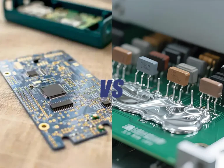
PCB soldering is the process of joining electronic components to a printed circuit board using molten solder.
When heated correctly, solder creates:
- 电导率
- Mechanical connection
- Stable signal transfer between components
Modern electronics mainly use two soldering methods:
- 通孔焊接
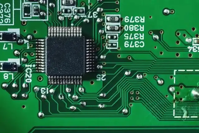
- Surface mount soldering (SMD/SMT)
Through-hole soldering is commonly used for connectors, transformers, and high-strength components. SMD soldering is used in compact modern electronics where components are mounted directly onto the PCB surface.
For modern PCB assembly and repair, understanding both methods is important.
Related guides:
- How to Solder SMD Components
- SMD vs Through-Hole Soldering
- What Is a Cold Solder Joint
Types of Solder Used in Electronics
Different solder types affect soldering temperature, flow behavior, and joint reliability.
含铅焊料
Leaded solder usually contains tin and lead alloys such as Sn63/Pb37.
优势
- Lower melting temperature
- 焊料流动顺畅
- Easier for beginners
- Faster wetting performance
It is still widely preferred in repair environments because it is easier to control during manual soldering.
无铅焊料
Lead-free solder is commonly used to comply with RoHS environmental regulations.
Compared with leaded solder, it:
- Requires higher temperature
- Oxidizes faster
- Has a narrower working range
Because of the higher thermal requirements, lead-free solder places greater stress on soldering tips and PCB surfaces.
Related guide:
Flux-core solder
Most electronics solder includes internal flux.
Common types:
- Rosin-core flux
- No-clean flux
Flux 能帮助:
- 去除氧化层
- 改善焊料的润湿性
- Increase heat transfer efficiency
Without proper flux activity, solder joints often become dull or unstable.
Related guide:
Essential Soldering Tools and Equipment
Proper equipment directly affects solder quality and repair efficiency.
烙铁
A soldering iron is used for direct point heating.
Basic models may work for simple tasks, but professional PCB repair usually requires temperature-controlled systems for stable heat delivery.
焊接站
A soldering station combines:
- 温度控制
- Stable power output
- Replaceable tips
Compared with basic irons, soldering stations provide:
- Better thermal recovery
- More consistent soldering performance
- Reduced overheating risk
Temperature stability becomes especially important during SMD work.
Related guide:
热风返修站
Hot air rework stations are used for:
- SMD元器件拆卸
- IC replacement
- PCB reflow repair
Instead of direct contact heating, they use controlled hot airflow to melt multiple solder joints simultaneously.
This is essential for modern SMT repair.
Related guides:
Desoldering station
Desoldering stations use heated suction systems to remove solder from through-hole joints.
They are commonly used for:
- Connector removal
- Pin extraction
- Hole cleaning during repair
Supporting tools
Additional tools improve soldering consistency and reduce repair risks.
Important supporting tools include:
- 通量
- Brass sponge
- Tip tinner
- 精密镊子
- PCB holders
- Magnification tools
How to Solder Properly
Correct soldering technique is more important than excessive temperature.
Prepare the PCB and components
Before soldering:
- Clean contaminated surfaces
- 去除氧化层
- Secure components properly
Contaminated pads reduce solder wetting performance.
Use the correct temperature
Typical soldering ranges:
- Leaded solder: 320°C–350°C
- Lead-free solder: 350°C–380°C
Higher temperature does not automatically improve solder quality.
Excess heat increases:
- 氧化
- PCB damage risk
- Tip wear
Related guide:
Heat the pad and lead together
Proper soldering requires heating both surfaces evenly.
The correct process:
- Touch iron to pad and component lead
- Allow surfaces to heat
- Feed solder into the joint
- Remove solder first
- Remove iron second
This creates stronger and more reliable solder joints.
Avoid excessive solder
Too much solder may create:
- 焊桥
- Hidden joint defects
- Inspection difficulties
A proper solder joint should appear smooth and evenly shaped.
Inspect the solder joint
Good solder joints usually appear:
- Smooth
- Shiny
- Evenly wetted
Bad joints may appear:
- Dull
- Cracked
- Grainy
- Uneven
Related guide:
How to Tin a Soldering Iron
Tinning means coating the soldering tip with a thin protective solder layer.
This process:
- Prevents oxidation
- Improves heat transfer
- Extends tip lifespan
Without proper tinning, soldering tips quickly become oxidized and difficult to use.
Why soldering tips oxidize
Soldering tips are exposed to:
- High temperature
- Oxygen
- Flux residue
Lead-free soldering accelerates oxidation because of its higher operating temperatures.
Proper tip cleaning methods
Professional technicians usually prefer:
- Brass wool
- Light sponge cleaning
Aggressive cleaning methods such as sandpaper can permanently damage plated tips.
Why re-tinning matters
Experienced technicians re-tin tips:
- Before soldering
- After cleaning
- Before storage
Leaving a thin solder coating protects the tip surface while cooling.
Related guides:
Common PCB Soldering Problems
Even experienced technicians encounter soldering defects during PCB repair and assembly.
Cold solder joints
Cold joints occur when solder fails to bond properly.
Common causes:
- Insufficient heat
- 冷却过程中的移动
- Oxidized surfaces
症状
- Weak electrical connection
- Intermittent circuit behavior
焊桥
Solder bridges happen when excess solder connects adjacent pads or pins unintentionally.
They are common during:
- Fine-pitch IC soldering
- Excess solder application
- Poor drag soldering technique
Oxidized soldering tips
Oxidized tips reduce heat transfer and prevent solder from wetting properly.
Common signs:
- Blackened tip surface
- Solder balling
- Uneven heating
Related guide:
Lifted PCB pads
Pads may detach from the PCB because of:
- Excessive heat
- Excessive force
- Improper rework technique
Multilayer boards are especially vulnerable to thermal damage.
焊料润湿不良
Poor wetting occurs when solder fails to spread smoothly across the pad surface.
Common causes:
- 氧化
- Dirty surfaces
- 助焊剂不足
- 温度不正确
PCB Rework and Desoldering Methods
PCB rework refers to removing, repairing, or replacing electronic components after the original soldering process.
Rework is common in:
- 电子产品维修
- Prototype modification
- Manufacturing defect correction
- Component replacement
Modern PCB rework requires controlled heat and proper solder removal techniques to avoid damaging pads or nearby components.
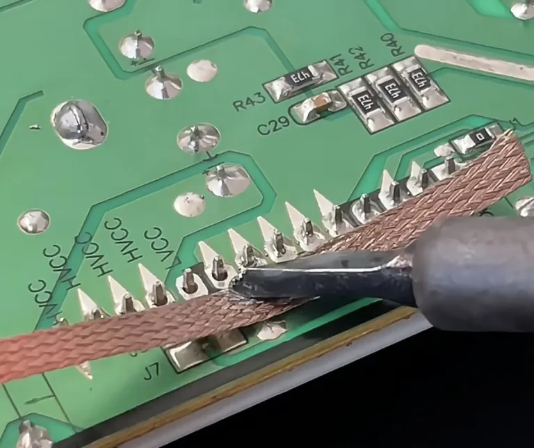
Solder wick method
Solder wick, also called desoldering braid, is used to absorb molten solder.
流程:
- Place braid on solder joint
- Apply heated soldering tip
- Allow solder to flow into braid
This method is effective for:
- Small solder bridges
- Pad cleanup
- Excess solder removal
Desoldering pump method
A desoldering pump removes molten solder using vacuum pressure.
它通常用于:
- 通孔元器件
- Connector removal
- Pin extraction
Compared with solder wick, vacuum desoldering is usually faster for large solder joints.
Hot air rework method
Hot air rework stations heat multiple solder joints simultaneously using controlled airflow.
They are widely used for:
- SMD IC removal
- QFP/QFN packages
- PCB reflow correction
- Surface-mounted component replacement
Proper airflow and temperature control are critical during hot air rework to prevent PCB overheating.
Related guides:
Replacing damaged components
Successful component replacement usually involves:
- Proper solder removal
- PCB pad cleaning
- Flux application
- Controlled resoldering
Forcing components off the board before solder fully melts is one of the main causes of pad damage.
SMD Soldering and Rework
SMD (Surface Mount Device) soldering is the standard method used in modern electronics manufacturing.
Unlike through-hole components, SMD parts are mounted directly onto the PCB surface.
Why SMD repair is more challenging
SMD components are:
- Smaller
- Densely packed
- More heat-sensitive
This increases the difficulty of:
- Heat control
- Component positioning
- Solder bridge prevention
Reworking IC chips
IC packages such as:
- QFP
- QFN
- SOP
- SOIC
usually require hot air rework because all solder joints must melt simultaneously.
Professional technicians often combine:
- 空谈
- 通量
- 精密镊子
- Temperature-controlled stations
to reduce PCB stress during removal.
Preventing pad damage during SMD work
Pad lifting is usually caused by:
- Excessive force
- Overheating
- Uneven heating
Proper technique involves:
- Gradual heating
- Flux application
- Gentle component removal
Why flux matters in SMD soldering
Flux improves:
- 传热
- Oxidation removal
- Solder flow consistency
Without proper flux, fine-pitch soldering becomes significantly more difficult.
Related guide:
Soldering Temperature Guide
Temperature control is one of the most important factors in PCB soldering and rework.
Incorrect temperature leads to:
- Poor solder joints
- 氧化
- PCB损坏
- Shortened tip lifespan
Leaded solder temperatures
Typical range:
- 320°C-350°C
Leaded solder melts more easily and usually provides smoother solder flow.
Lead-free solder temperatures
Typical range:
- 350°C–380°C
Lead-free solder requires more thermal energy and oxidizes faster during extended work.
Related guide:
Hot air rework temperature ranges
Typical hot air settings:
- Small SMD work: 280°C–320°C
- Lead-free IC rework: 320°C–380°C
Actual settings depend on:
- PCB thermal mass
- 元件尺寸
- Airflow level
- 喷嘴尺寸
Why excessive heat damages PCB
Excess temperature may cause:
- 加高垫片
- Burned PCB surfaces
- 部件故障
- 电路板层间分层
Controlled heat is always safer than maximum heat.
Professional Tips for Better PCB Rework
Experienced technicians focus on thermal control and consistency rather than speed alone.
Use proper flux
Flux improves:
- Solder flow
- 传热
- Joint reliability
Poor flux usage is one of the most common causes of difficult soldering.
Keep soldering tips tinned
A properly tinned tip:
- 高效传热
- Resists oxidation
- Improves solder flow
Tips should be re-tinned regularly during work sessions.
Use stable temperature stations
Temperature fluctuations create inconsistent solder joints.
Professional soldering stations provide:
- Faster thermal recovery
- More stable heat output
- Better performance during continuous work
Control airflow during rework
Excess airflow may:
- Blow away components
- Cool joints unevenly
- Reduce heating efficiency
Low controlled airflow is often more effective than maximum airflow.
Avoid excessive pressure
Pressing soldering tips too hard:
- Damages pads
- Reduces tip lifespan
- Causes uneven heat transfer
Proper heat should do the work, not force.
Safety Tips for Electronics Soldering
Electronics soldering involves high temperature, fumes, and sensitive electronic components.
Proper safety practices are essential.
Ventilation and fumes
Soldering fumes should not be inhaled continuously.
推荐做法:
- Use ventilation systems
- Use fume extractors
- Maintain airflow in work area
静电放电(ESD)防护
Electrostatic discharge can damage sensitive electronic components.
Professional workstations often use:
- ESD-safe soldering stations
- Grounded mats
- Wrist straps
Heat safety
Soldering tools operate at temperatures above 300°C.
Always:
- Return tools to holders
- Avoid touching heated metal parts
- Allow stations to cool properly before storage
PCB handling precautions
Avoid:
- Excess bending
- Direct mechanical stress
- Overheating localized areas
Multilayer boards are especially sensitive during rework.
常见问题解答
What temperature should I solder at?
Most electronics soldering is performed between 320°C and 380°C depending on solder type and PCB structure.
Why won’t solder stick to my tip?
常见原因包括:
- Oxidized tip
- 助焊剂不足
- 温度不正确
- Contaminated surfaces
Is lead-free solder harder to use?
Yes. Lead-free solder requires higher temperature and oxidizes faster than leaded solder.
Can hot air damage PCB?
Yes, if airflow or temperature is too high. Controlled heating is critical during rework.
What is the difference between soldering and rework?
Soldering refers to original component assembly, while rework involves repairing, replacing, or correcting existing solder joints.
How long do soldering tips last?
Tip lifespan depends heavily on:
- 温度控制
- Proper tinning
- Cleaning habits
- Solder type used
Do professionals use hot air stations?
Yes. Hot air rework stations are standard equipment in modern SMT repair and PCB maintenance.
结论
PCB soldering and rework require more than basic tools. Proper temperature control, flux usage, tip maintenance, and repair technique all directly affect solder joint reliability and PCB safety.
As modern electronics continue moving toward compact SMT designs, hot air rework and precision soldering become increasingly important in both manufacturing and repair environments.
Using the correct equipment and proper soldering practices helps improve repair efficiency, reduce PCB damage, and extend tool lifespan.
Professional Soldering & PCB Rework Solutions from GORDAK
GORDAK provides professional soldering stations, hot air rework systems, and PCB repair equipment designed for stable temperature control, precision rework, and long-term industrial reliability.
For OEM/ODM cooperation and global distribution inquiries, contact: info@gordakelec.com